SFC-60 Assembly guide
About the build
What you’ll find in your kit :
Start by opening all the bags of parts and organize them on your desk. Be careful not to loose any of the small pieces.
The enclosure panels in your kit are covered with a blue protective plastic film. Remove it before trying to assemble the enclosure.
Things you will need :
– The best soldering iron you get can your hands on
– Soldering wire (around 0.5mm for small pins, for big pins 1mm can be easier but is optional – lead-free solder with a “no-clean” flux core is our recommendation)
– Flush cutters
– De-soldering pump (optional)
– Desoldering wick (optional)
– A good amount of time and patience. Don’t rush it and triple-check everything that you’re doing. Trying to fix mistakes after the fact is much more work than doing it correctly right away
Disclaimer : We are not responsible for anything wrong (including damaging the PCB or parts, electric shocks, malfunctions, fires, accidents involving a soldering iron) that might happen during the assembly of the kit. Everything you do while assembling the kit is at your own risks. Respect basic safety rules when soldering.
We’ll start with the front side of the PCB. Which means that we will insert parts in the front of the PCB (the side you can see the SoundForce logo on) and we’ll flip the PCB to solder the parts in place.
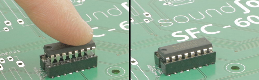
IC sockets : FRONT SIDE – PCB VIEW (Right-click and open in a new window)
IC’s : FRONT SIDE – PCB VIEW (Right-click and open in a new window)
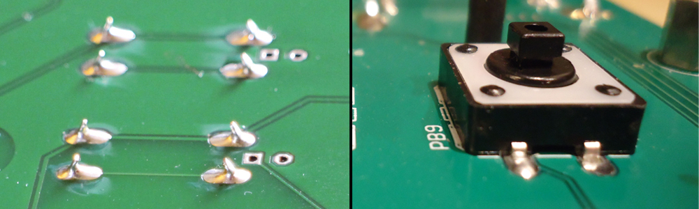
Tact Switches : FRONT SIDE – PCB VIEW (Right-click and open in a new window)
Faders : FRONT SIDE – PCB VIEW (Right-click and open in a new window)
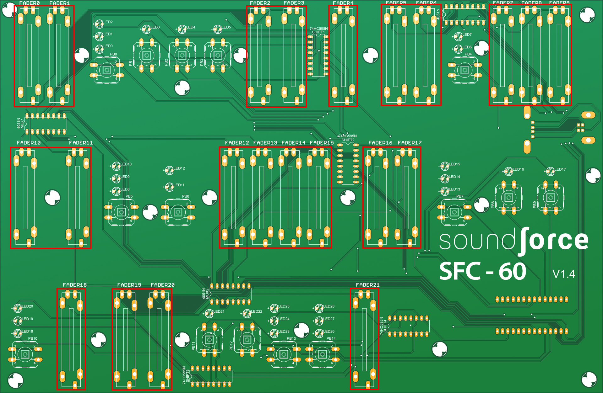
You need to make sure that every fader is straight and flush against the PCB surface before you solder them. Start by placing the first fader in position like this (push until it’s all the way inside the holes) :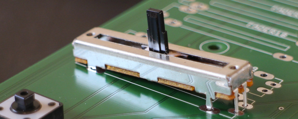
Then holding the fader in place, flip the board and bend 2 legs of the fader like this :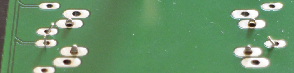
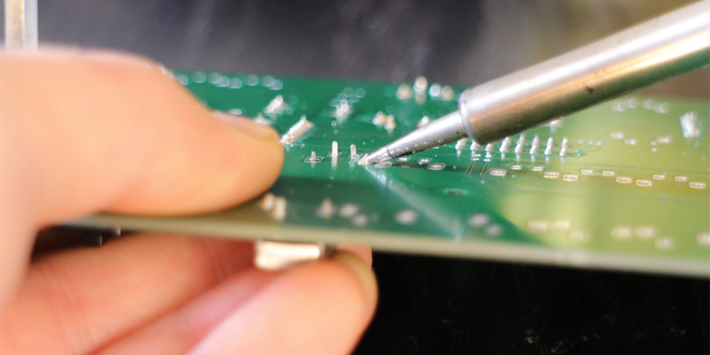
You can now go ahead and solder ONLY ONE of the 4 side mounting legs (the bigger pins) like this :
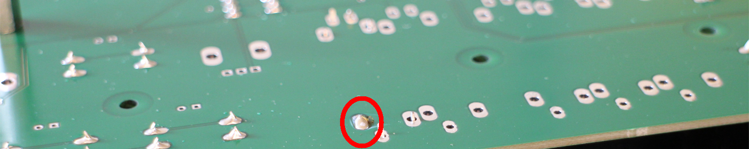
When the solder joint is completely cooled down, hold the PCB and the fader with one hand (use your thumb on the fader on the bottom of the PCB). With your other hand reheat the pad with the iron. When you see the solder re-flow (getting fluid again) push firmly against the center of the fader to bring it as far as possible inside the holes (you might have to use a glove as the back of the fader can get hot), then remove the iron from the joint and wait until the solder soldifies again to remove your thumb:
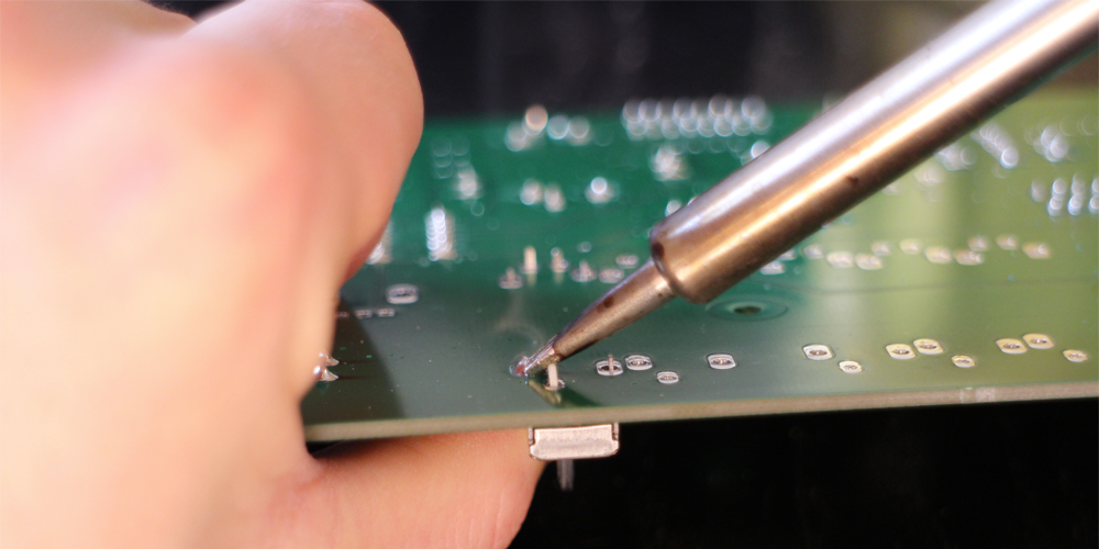
Solder now the other mounting leg across on the other side :
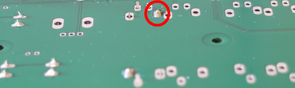
The reheat this leg and push on the back of the fader again as you did with the other leg :
The fader is now locked straight in place and you can solder the remaining 2 mounting legs and 3 signal pins of the fader. Repeat those steps for the remaining faders.
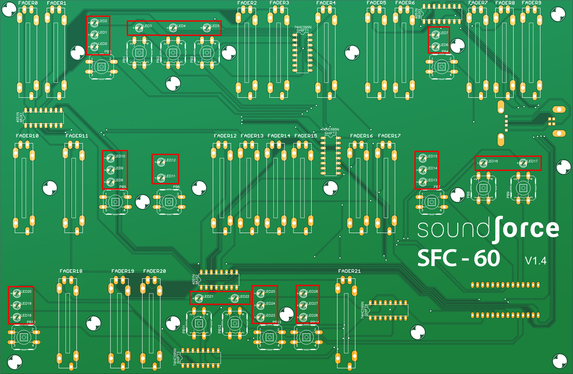
Leds and holders : FRONT SIDE – PCB VIEW (Right-click and open in a new window)
Place the 29 LEDs into their holders and make sure they’re flush against the holder surface.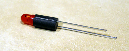 Insert the LED in place, the longer lead of each LED is going into the “+” pad and the shorter lead in the “-” pad.
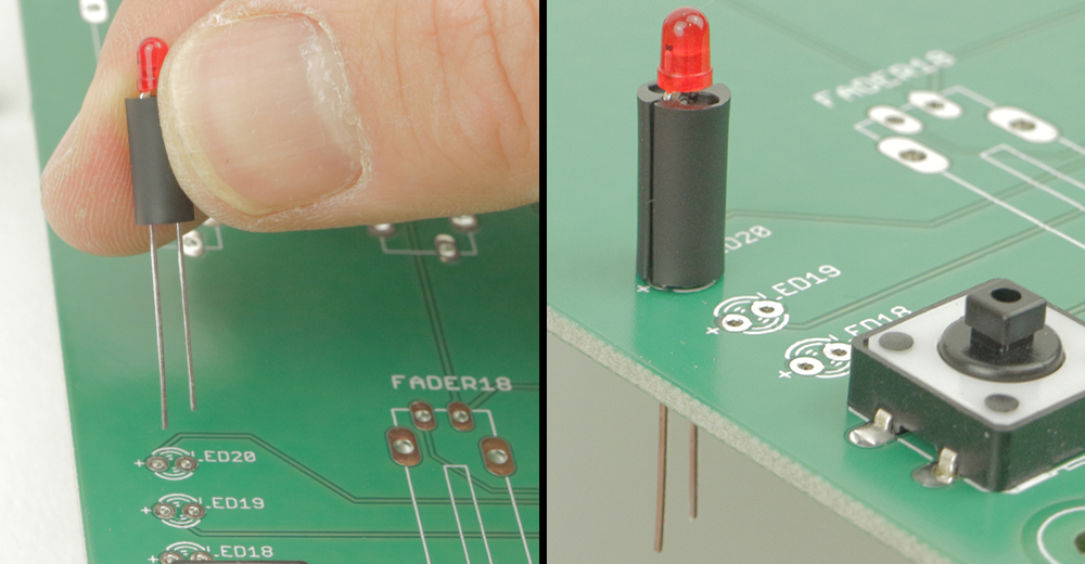 Bend the LED leads at the back of the PCB at about a 45deg angle. Pull a bit of the leads when bending them to get the LED flat on the surface of the PCB.
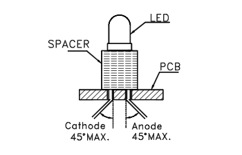 Repeat this for the 28 remaining LEDs. Then flip the PCB and solder just 1 pin of every LED. Use just a small amount of solder as those pins are very small. Temporarily placing the front panel on top can help to see if everything will fit. Make sure that everything is straight and then solder the 28 other second pins. When you’re done, cut off the rest of the lead that is sticking out of the bottom of the PCB. Do it one lead at the time. This is the result you are looking for :
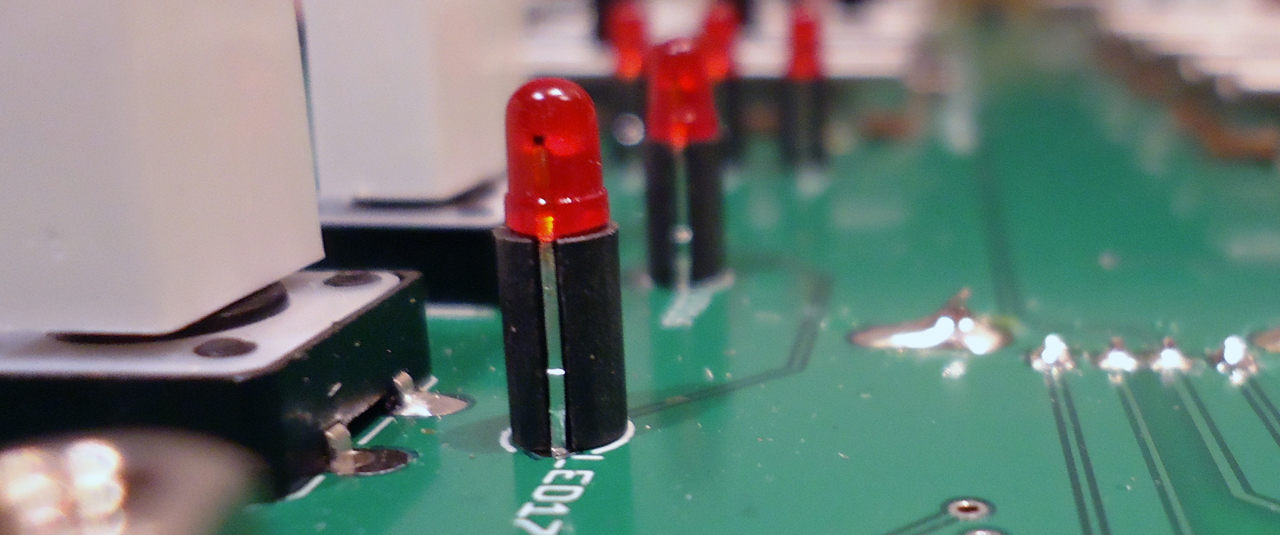 FIY, those LEDs have integrated resistors; that’s why no resistors are included in the kit.
The next parts need to get soldered at the BACK of the PCB.
Teensy sockets: BACK SIDE – PCB VIEW (Right-click and open in a new window)
Enclosure assembly :
Once you’re sure that the controller is working, you can assemble the enclosure. Screw the 7 remaining 7+25 spacers together. 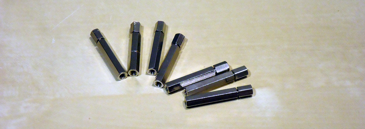 Screw the PCB on the bottom panel using 19 screws. Then screw the 7+25 spacers to the bottom panel on the remaining 7 outside holes:
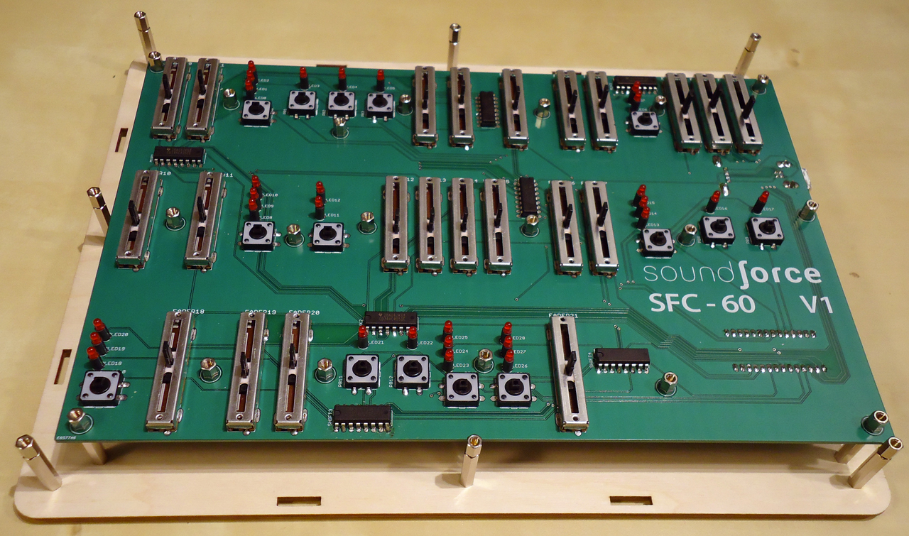 Insert the sides in the bottom panels starting by the right side (where the USB connector is). The notches on the panels are there to help you assemble it properly:
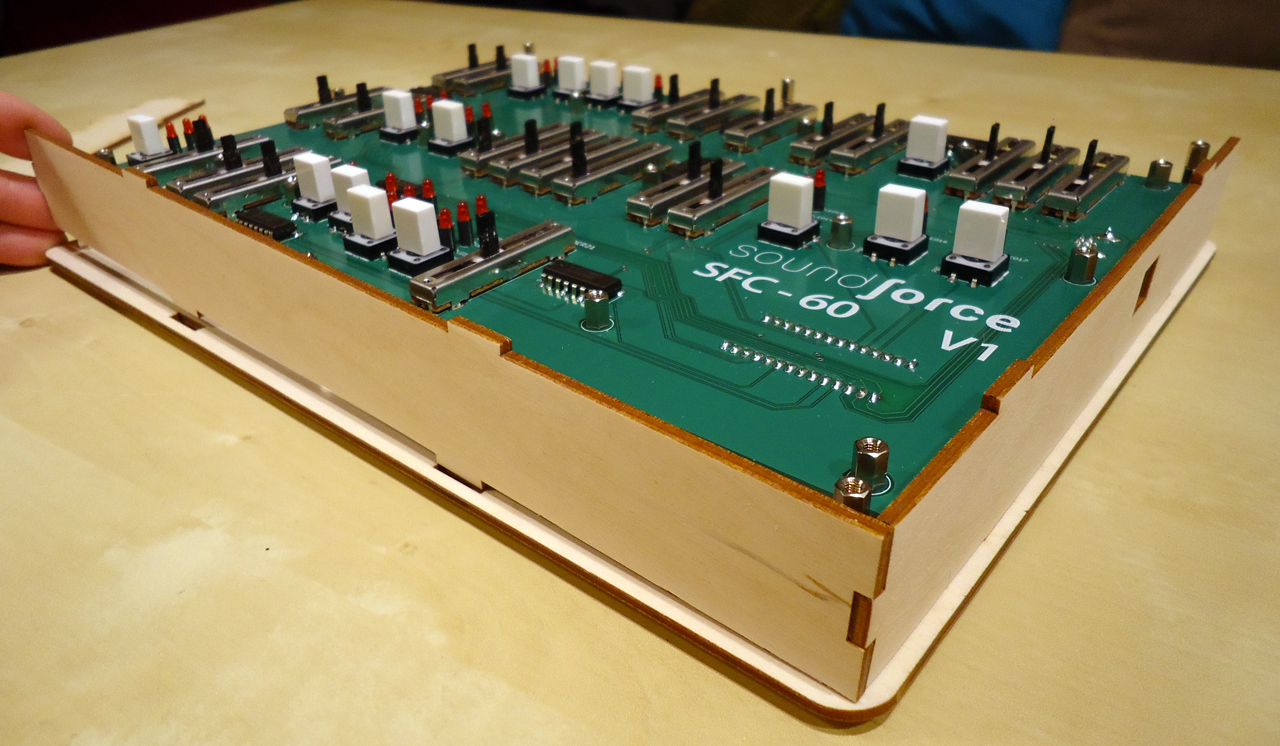 Insert the front panel into the side notches (you might need to give it a little pressure):
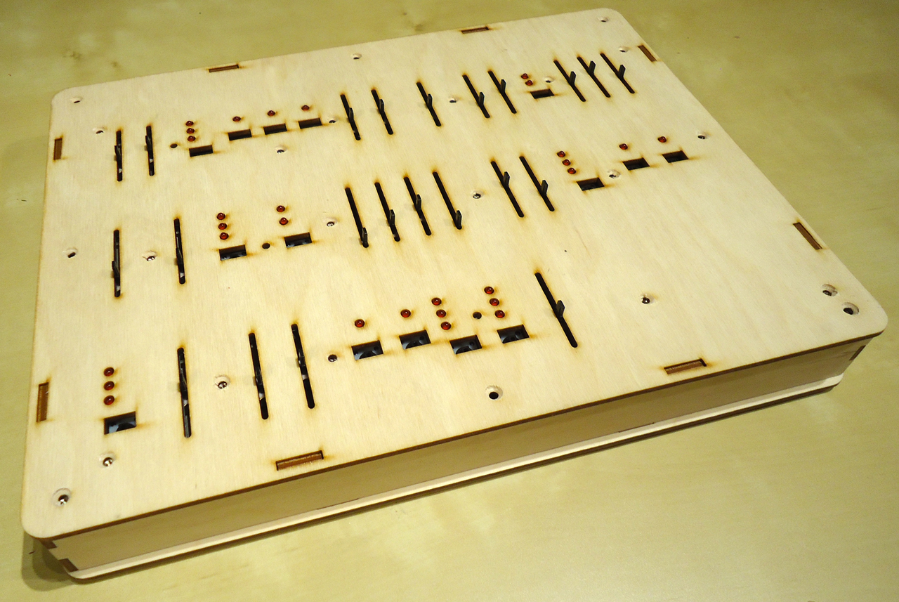 Attach it with the 8 nylon M3 screws. Turn the controller over and apply the 4 bumper feet on the 4 small holes at each corner. They peel right off the support sheet. Then insert the 22 fader caps and the 15 tact switches caps.
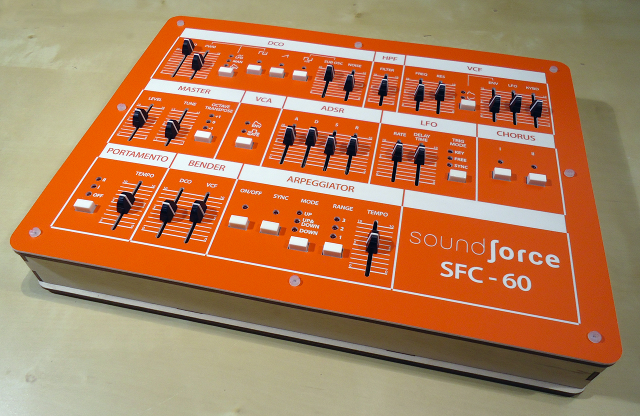 You’re done! Congratulations. Enjoy your SFC-60 MIDI controller. Check our the manual on our support page with the DAW set-up.
Troubleshooting
– If one isolated LED is not working, you probably soldered it the wrong way around. You can apply a 5V power source (with the USB cable disconnected) on the pins of the LED to check if that’s the problem before you try to unsolder it.
– The switches are connected directly to the Teensy micro-controller. If one switch is not working, check its solder joints.
– If nothing happens when you plug the USB cable in the USB-B connector, try connecting the Teensy directly into the computer. If it is then working, there is most likely a connection problem with the 2 USB connectors. The signal pins of the connectors are very small; check if you didn’t short circuit them.